Learning Unity and C#
Unity is a game engine tool that allows me to simulate the projection with the encoded mathematical formula. The engine has its library built on top of the C# language utilizing object-oriented programming. Although I don’t have any experience with C# before, it is easy to learn with previous programming experiences.
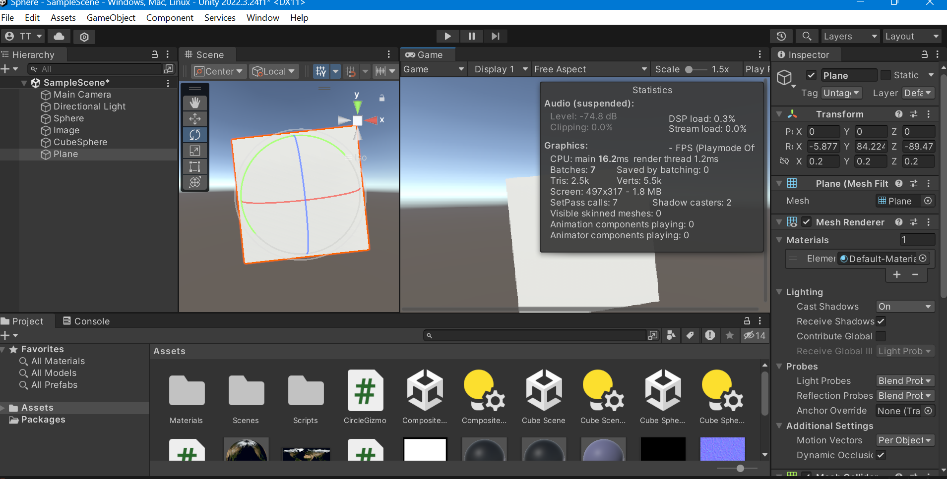
The main GUI has 5 main components: the hierarchy, the view, the inspector, the project window, and the console. The hierarchy lists all the game objects such as the camera, light source, and other custom game objects. After clicking on a game object, the inspector will show an editor where developers can edit anything related to that object such as changing position, applying material, or adding C# script. Once a script is used, developers can press the play button to enter play mode. In this mode, the game scene will show exactly how the scene is from the camera position and angle. Furthermore, any errors will be printed in the console at runtime.
Below is the sample main UI of Unity:
Simulate projection mapping and UV mapping in Unity
Building onto the math for projection mapping, I wrote a function to create an image to be projected onto a sphere. First, I declare public variables that can be updated in the inspector in GUI. For example, in the inspector view, I can just drag and drop an image file to assign it to the “texture” variable to be used in this script.
    public int LIGHT_TO_IMAGE = 1;
    public int LIGHT_TO_SPHERE = 5;

    public Texture2D texture;
    public float Radius = 1;
    public float Step = 0.1f;
Then, I wrote a function getImage() to spawn a new texture file and apply it to the Plane object. This texture will have every coordinate mapped to pixels of the Earth’s texture.
    public Vector3[] getImage(){
       const int HALF_TEXTURE_SIZE = 50;
        const int TEXTURE_SIZE = HALF_TEXTURE_SIZE * 2;
        Texture2D projected = new Texture2D(TEXTURE_SIZE, TEXTURE_SIZE);
        GameObject image = GameObject.Find("Plane");
        image.GetComponent<Renderer>().material.mainTexture = projected;

        //get all vertices for x >= 0

        for (float x = 0.2f; x <= Radius; x += Step)
        {
            for (float z = -Radius; z <= Radius; z += Step)
            {

                //use sphere equation to solve for y
                //x^2 + z^2 + y^2 = r^2
                float _y = Mathf.Sqrt(Mathf.Pow(Radius, 2) - Mathf.Pow(x, 2) - Mathf.Pow(z, 2));
                float[] ys = {_y, -_y};

                foreach ( float y in ys)
                {
                    //get coordinate of the projected image;
                    //CenterLine is a line connecting light, image's center and sphere origin
                    float distOfPt_CenterLine = Mathf.Sqrt(Mathf.Pow(y, 2) + Mathf.Pow(z, 2));
                    //the two triangles are similar :
              //(LIGHT, SPHERE ORIGIN, POINT ON SPHERE) and (LIGHT, IMAGE CENTER, PROJECTED POINT ON IMAGE)

                    float distOfProjPt_Center = distOfPt_CenterLine / (LIGHT_TO_SPHERE - x) * LIGHT_TO_IMAGE;
                    float angleOfProjPt_ZAxis = Mathf.Atan(y / z);
                    float i = Mathf.Sin(angleOfProjPt_ZAxis) * distOfProjPt_Center ;
                    float j = Mathf.Cos(angleOfProjPt_ZAxis) * distOfProjPt_Center * Mathf.Abs(z) / z;

                    if (!float.IsNaN(i) && !float.IsNaN(j))
                    {
                        //Tmax is the upperbound of the projected image
                        //TODO: find max programmatically using tangent line
                        float max = 0.203f;

                        i = map(i, max, HALF_TEXTURE_SIZE) + HALF_TEXTURE_SIZE;
                        j = map(j, max, HALF_TEXTURE_SIZE) + HALF_TEXTURE_SIZE;

                        //get pixel of the texture coordinate

                        //mapping u and v coordinate in range [0, 1]
                        float u = 0.5f + Mathf.Atan2(z, x) / (2 * Mathf.PI);
                        float v = 0.5f + Mathf.Asin(y) / Mathf.PI;
                        u = map(u, 1, texture.width);
                        v = map(v, 1, texture.height);
                        //get color of the texture by the coordinate
                        Color color = texture.GetPixel((int)u, (int)v);
                        projected.SetPixel((int)i, (int)j, new Color(0, 0,  1, 1));
                    }
                }

            }
        }
    }
Here is the result (not as expected):
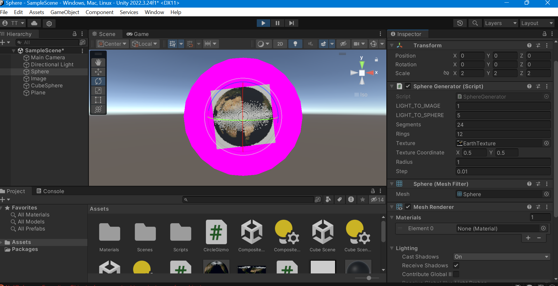
Connection to the project
More work needs to be done for the image to be mapped correctly. I haven’t understood what is causing the pattern yet or why there are unmappable points. I plan to implement algorithms to clarify if there are repeated coordinates such as drawing lines between a point on the sphere to a point rendered on a texture file.